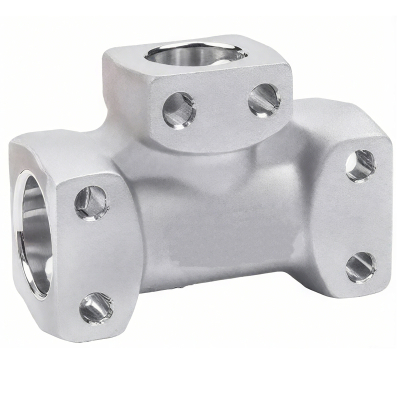
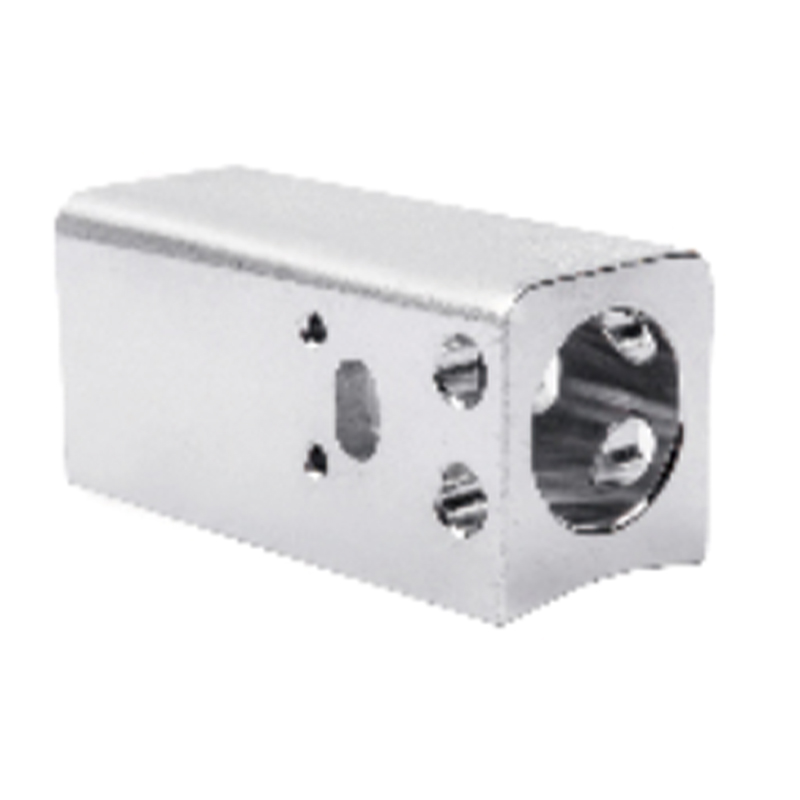
A series of connectors for hydraulic cylinders
1. Reliable connection
2. Pressure resistance and wear resistance
3. Easy installation
4. High adaptability
Product Introduction
Hose connections are designed with an emphasis on reliability, ensuring tight and stable connections under high pressure and dynamic conditions. The use of high quality materials provides increased strength and durability, preventing the joint from deforming or breaking under pressure. In addition, the connection includes elements such as cotter pins, circlips and O-rings to ensure a tight and stable connection.
The joints are able to withstand high pressure while maintaining their shape and functional integrity. Even after prolonged use there are no signs of material fatigue or damage.
The quick-release design allows for quick replacement or maintenance, reducing downtime. Some connections feature convenient locking mechanisms (such as lever or key locks), making installation and removal easy without the need for special tools.
High pressure hose couplings are designed to withstand a variety of operating conditions, including extreme temperatures, humidity levels and chemical conditions. They are suitable for various media such as oil, water, air and chemical solvents. Hence, they are used in various industrial fields including coal mining, chemical processing, construction and agriculture. Their resistance to vibration and shock ensures stable operation in dynamic or unstable operating conditions.
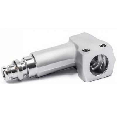
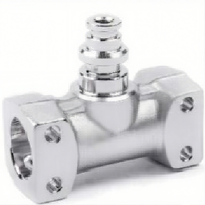
Product model with safety valve (left)
Model |
FD |
FD1 |
FD2 |
A |
L |
L1 |
T |
R |
DJZ24×39-2 |
8.5 |
39 |
24 |
36 |
55 |
66 |
50 |
145 |
DJZ24×39-3 |
8.5 |
39 |
24 |
36 |
55 |
69 |
50 |
245 |
DJZ24×39-4 |
8.5 |
39 |
24 |
40 |
55 |
75 |
67 |
290 |
Product model with socket (right)
Model |
FD |
FD1 |
FD2 |
A |
L |
G |
T |
R |
Z22×109-1 |
20 |
22 |
4.2 |
21 |
109 |
48.5 |
46 |
80 |
Z22×109-2 |
20 |
22 |
4.2 |
21 |
109 |
48.5 |
46 |
145 |

Parameters of the pipe fittings block (left)
Modelb |
Size |
D |
D1 |
Knock |
A |
L |
L1 |
T |
R |
JDZ13F13-1 |
DN13 |
6 |
24 |
18 |
22 |
85 |
56 |
49 |
80 |
Jdz19f19-1 |
DN19 |
6 |
29 |
24 |
27 |
98 |
68 |
56 |
80 |
Jedz 19f19-2 |
DN19 |
6 |
29 |
24 |
27 |
98 |
68 |
56 |
145 |
JKZ13F13-1 |
KJ13 |
5.5 |
22 |
18 |
20 |
85 |
56 |
49 |
80 |
JKZ19F19-1 |
KJ19 |
6.8 |
28 |
24 |
26 |
98 |
68 |
56 |
80 |
JKZ19F19-2 |
KJ19 |
6.8 |
28 |
24 |
26 |
98 |
68 |
56 |
145 |
Pipe coupling parameters (right)
Model |
L |
G |
T |
R |
GZ10 |
35 |
46 |
40 |
80/145 |
GZ13 |
35 |
46 | 40 |
80/145/235/290 |
GZ16 |
40 |
54 |
40 |
80/145 |
GZ19 |
44 |
57 |
48 |
80/145 |

Technical characteristics of the corner joint
Model |
Size |
FD |
FD1 |
FD2 |
FD3 |
A |
A1 |
L |
L1 |
T |
JDZ10×10 |
DN10 |
6 |
20 |
14 |
13.5 |
18 |
60 |
90 |
52 |
45 |
JDZ13×13 |
DN13 |
6 |
24 |
18 |
13.5 |
22 |
60 |
90 |
56 |
45 |
JDZ16×16 |
DN16 |
6 |
26 |
21 |
13.5 |
24 |
60 |
90 |
54 |
48 |
JDZ19×19 |
DN19 |
6 |
29 |
24 |
13.5 |
27 |
60 |
90 |
58 |
48 |
JKZ10×10 |
KJ10 |
5.5 |
18 |
15 |
13.5 |
16 |
60 |
90 |
52 |
45 |
JKZ13×13 |
KJ13 |
5.5 |
22 |
18 |
13.5 |
20 |
60 |
90 |
56 |
45 |
JKZ16×16 |
KJ16 |
6.8 |
25 |
20 |
13.5 |
22 |
60 |
90 |
54 |
48 |
JKZ19×19 |
KJ19 |
6.8 |
28 |
24 |
13.5 |
26 |
60 |
90 |
58 |
48 |
Corner connection model
Model |
Size |
FD |
FD1 |
FD2 |
A |
L |
L1 |
no |
R |
Jujd19-1 |
DN19 |
6 |
29 |
24 |
27 |
72 |
54.6 |
65 |
80 |
Jujdar19-2 |
DN19 |
6 |
29 |
24 |
27 |
72 |
54.6 |
65 |
145 |
Jujk19-1 |
KJ19 |
6.8 |
28 |
24 |
26 |
72 |
54.6 |
65 |
80 |
Jujk19-2 |
KJ19 |
6.8 |
28 |
24 |
26 |
72 |
54.6 |
65 |
145 |

Connector parameters (left)
Model |
Size |
FD |
FD1 |
FD2 |
L |
R |
JD10 |
DN10 |
6 |
20 |
14 |
42 |
80/145 |
JD13 |
DN13 |
6 |
24 |
18 |
42 |
80 |
JD19 |
DN19 |
6 |
29 |
24 |
50 |
80/145 |
JK10 |
KJ10 |
5.5 |
18 |
15 |
42 |
80/145 |
JK13 |
KJ13 |
5.5 |
22 |
18 |
42 |
80 |
JK19 |
KJ19 |
6.8 |
28 |
24 |
50 |
80/145 |
Connector block parameters (center)
Model |
Size |
FD |
FD1 |
FD2 |
L |
T |
R |
KJD10×10 |
DN10 |
6 |
20 |
14 |
45 |
34 |
80/145 |
KJD13×13 |
DN13 |
6 |
24 |
18 |
48 |
38 |
80/145 |
KJD16×16 |
DN16 |
6 |
26 |
21 |
44 |
40 |
80/145 |
KJD19×19 |
DN19 |
6 |
29 |
24 |
50 |
44 |
80/145 |
KJK10×10 |
KJ10 |
5.5 |
18 |
15 |
45 |
34 |
80/145 |
KJK13×13 |
KJ13 |
5.5 |
22 |
18 |
48 |
38 |
80/145 |
KJK16×16 |
KJ16 |
6.8 |
25 |
20 |
44 |
40 |
80/145 |
KJK19×19 |
KJ19 |
6.8 |
28 |
24 |
50 |
44 |
80/145 |
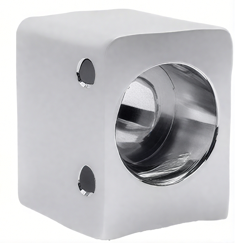
Connector body parameters (right)
Model |
Size |
FD |
FD1 |
FD2 |
A |
L |
L1 |
T |
R |
WJD10 |
DN10 |
6 |
20 |
14 |
18 |
52 |
46 |
28 |
80/145 |
WJD13 |
DN13 |
6 |
24 |
18 |
22 |
60 |
53 |
34 |
80/145/235/290 |
WJD16 |
DN16 |
6 |
26 |
21 |
24 |
60 |
52 |
40 |
80 |
Vajra19 |
DN19 |
6 |
29 |
24 |
27 |
65 |
57 |
40 |
80/145 |
WJD25 |
DN25 |
8.5 |
39 |
31 |
36 |
76 |
71 |
50 |
145 |
WJK10 |
KJ10 |
5.5 |
18 |
15 |
16 |
52 |
46 |
28 |
80/145 |
WJK13 |
KJ13 |
5.5 |
22 |
18 |
20 |
60 |
53 |
34 |
80/145/235/290 |
WJK16 |
KJ16 |
6.8 |
25 |
20 |
22 |
60 |
52 |
40 |
80/145 |
And your face 19 |
KJ19 |
6.8 |
28 |
24 |
26 |
65 |
57 |
40 |
80/145 |

Control valve seat parameters
Model |
L |
L1 |
no |
Oh |
L4 |
n-K |
T |
R |
KZFZ10×32×28-2 |
28 |
32 |
48 |
82 |
66 |
6-M8 |
43 |
145 |
KZFZ10×48×32-2 |
28 |
32 |
48 |
108 |
68 |
6-M8 |
45 |
145 |
KZFZ10×78×33-2 |
78 |
/ |
/ |
108 |
55 |
2-M10 |
45 |
145 |
KZFZ19×63×37-2 |
63 |
37 |
/ |
85 |
58 |
4-M10 |
60 |
145 |
KZFZ19×63×37-3 |
63 |
37 |
/ |
85 |
58 |
4-M10 |
60 |
235 |
KZFZ19×65×38-3 |
65 |
38 |
/ |
111 |
85 |
4-M12 |
80 |
235 |
KZFZ30×65×38-4 |
65 |
38 |
/ |
111 |
85 |
4-M12 |
80 |
290 |
KZFZ30×72×50-4 |
72 |
50 |
/ |
126 |
80 |
4-M12 |
80 |
290 |
KZFZ30×123×28-4 |
123 |
28 |
/ |
165 |
85 |
4-M16 |
80 |
290 |
KZFZ30×125×37-4 |
125 |
37 |
/ |
155 |
90 |
5-M12 |
80 |
290 |